 跳到内容

Grid-optic LED linear lighting is often chosen when a project needs long, orderly runs but does not want a continuous bright diffuser dominating the ceiling. The cellular or louvered aperture can help control high-angle brightness, while linked modules can create a coherent line. Yet the grid itself does not guarantee visual comfort. Its success depends on the room, mounting method, run geometry, photometry, joints and service plan.
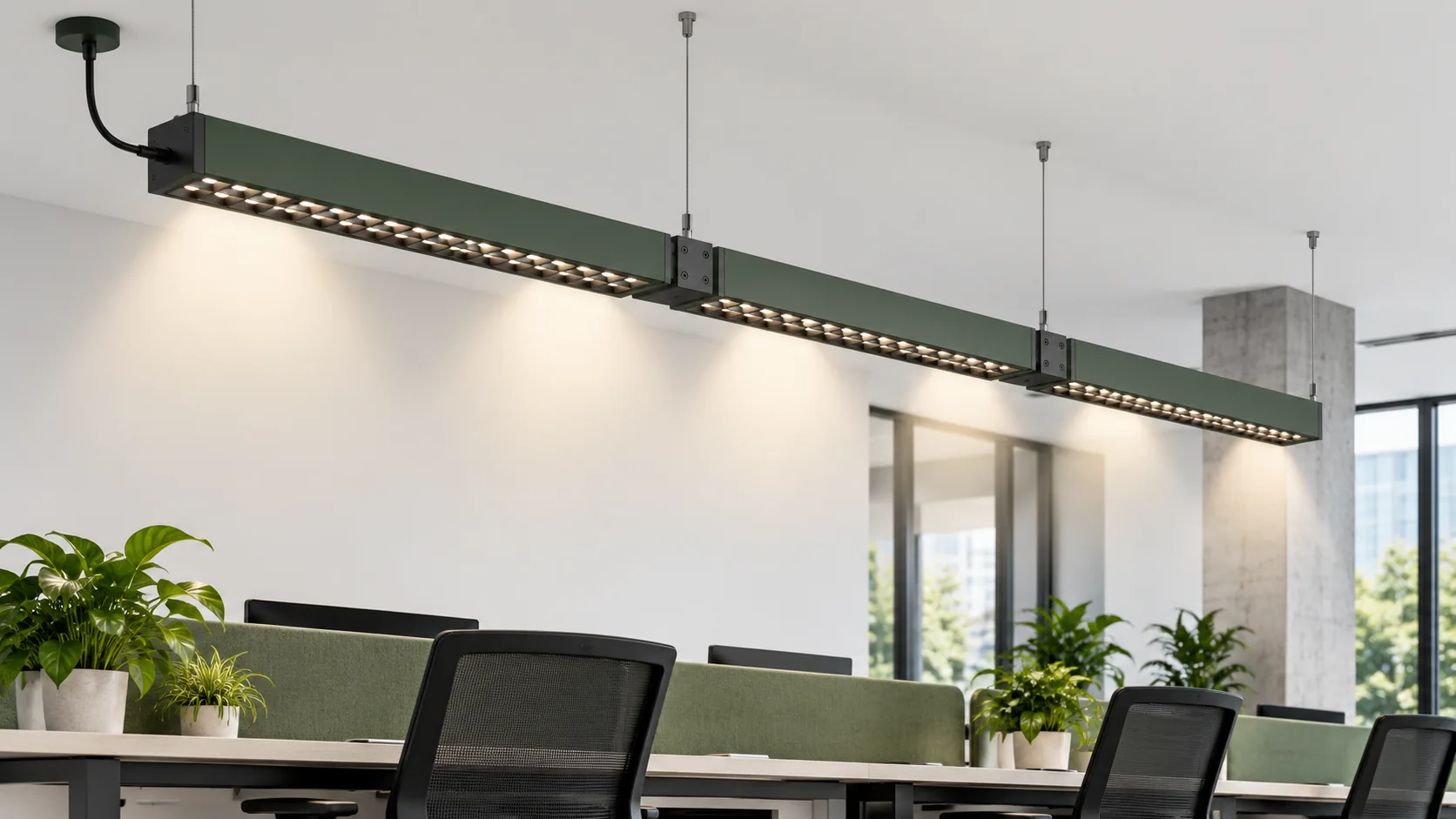
This guide explains how to plan modular grid-optic linear runs for offices, reception areas, retail circulation and similar commercial spaces. LCB’s customizable grid LED linkable linear lighting is a product starting point. Confirm the exact optic, output, length, controls and mounting details for any real project.
Start with the task, not the aperture
A grid optic is a visual and optical choice, not a complete lighting design. Document the surfaces to be illuminated: desks, circulation routes, counters, merchandise or architectural features. Identify the intended mood and which viewpoints matter. A fitting that looks pleasantly shielded from one seated position can appear bright from another, especially along the axis of a long run.
Draw the room in plan and section. Include ceiling height, workstation or shelf layout, partitions, ceiling services and daylight openings. An evenly spaced pattern of linear lights may be attractive on a reflected ceiling plan but miss the actual tasks below. The fixture layout should support the space as used, not just the ceiling geometry.
Ask the supplier for the photometric file corresponding to the exact grid and output. A family-level file may not reflect the selected aperture, diffuser or module length. Model the actual run and review the lighting from likely observer positions.
What does a grid optic change?
Cellular optics and louvers restrict direct views of the bright source in certain directions. This can make an aperture look quieter than an exposed LED strip or a broadly glowing diffuser. It can also alter beam shape, spacing needs and apparent brightness. Grid depth, cell shape, reflective finish and LED position all matter. “Anti-glare” is therefore a direction for evaluation, not a room-wide guarantee.
Compare the proposed grid with an opal or prismatic alternative under the same room conditions. A stronger cutoff can improve comfort from some sightlines while requiring more careful spacing to avoid an uneven task plane. A luminous diffuser may make the ceiling appear softer but expose more bright area. The right choice depends on the actual workspace and aesthetic intent.
Inspect a sample both lit and unlit. A dark grid can create a technical, restrained ceiling appearance; a pale finish can blend into a lighter ceiling. The finish should be approved alongside the surrounding architecture, not after the electrical package is fixed.
Plan the run as a system of modules
Linkable linear lighting is assembled from defined segments, connectors, feeds and end treatments. Build a run schedule before quoting: room and run ID, segment lengths, start and end coordinates, mounting type, feed point, control zone and finishing parts. If the appearance depends on equal cells or a regular pattern, check how the pattern behaves at joints and ends. A run that is mathematically centered may still end with an awkward half-module near the doorway.
Ask the supplier to provide the visible and electrical details of a joint. Is the grid pattern continuous? Is there a dark gap or bright point? How does the connector carry power and control? What is the maximum permissible linked run for the selected version? Do not calculate the run limit from a marketing photo or assume that a long visual line can be fed from one end.
For suspended runs, coordinate suspension points with segment joints, ceiling structure and any acoustic or mechanical services. For recessed runs, check the cutout and ceiling support. The installation strategy must match the exact product, not simply another linear luminaire from the same catalog.
Use ceiling and furniture grids intelligently
Many offices have a strong ceiling tile or acoustic grid. Aligning a linear run with that rhythm can help the space feel ordered. But a strict ceiling alignment is not always best for desks or circulation. Check the task plane first, then refine the visual alignment within the acceptable lighting range. A small aesthetic shift is preferable to lighting the aisle brilliantly while leaving workstations dim.
For open-plan areas, review at least one plausible furniture rearrangement. The layout does not need to be infinitely flexible, but it should not depend on one unusually specific desk position. Define which zones must remain usable if partitions move.
In retail spaces, grid optics can work for controlled general light or circulation, while accent heads or shelf lighting handle the merchandise. Do not force one fixture type to perform every layer. A clear hierarchy of ambient, vertical and focal lighting often gives a better result than multiplying linear runs.
Check glare in the real room
Glare is influenced by luminance, viewing angle, luminaire size, placement and room reflectances. A low advertised UGR figure is not a universal property that follows the fitting into every layout. Review the calculation for the selected room and optic, then inspect a representative installation from seated and standing positions. Look along and across the run; the two directions may feel different.
Screen-heavy workspaces need particular care. Identify the normal screen orientation, bright reflections and direct views into the aperture. A sample installed at the right height can reveal issues that a close-up product photograph cannot. Record the approved mounting position and optic code.
For a discussion of continuous runs and maintenance, see the driver-access and serviceable-runs guide. Optical comfort and service access should be resolved together before the ceiling is closed.
Controls and commissioning
Decide how runs will be switched, dimmed and zoned. A long continuous-looking line may cross several occupancy or daylight zones. If so, the electrical design must allow the visual continuity while giving the desired control behavior. Specify the exact driver, protocol and emergency-lighting interface where applicable.
At commissioning, test the full scene rather than only energizing the fittings. Check dimming smoothness, color consistency, joint appearance and the relationship to daylight and adjacent accent lighting. Label modules and control zones so maintenance teams can identify a faulty section without dismantling the wrong run.
Confirm the project’s local electrical and safety requirements separately. The suitability of a luminaire for a jurisdiction depends on the exact version and evidence supplied; this general guide is not a compliance certificate.
Service access is part of the design
Identify the driver position and the intended replacement method. Some projects prefer a remote driver in an accessible location; others use integrated or module-level drivers. Each approach has consequences for wiring, ceiling access and replacement labor. Ask whether LED boards, optics, grids and connectors can be replaced, and whether matching parts will be available for the expected maintenance period.
For visible continuous runs, a replacement module also needs a compatible finish and color appearance. Plan spares for a whole project, not just individual electronic components. Record batch, configuration and module position in the handover file. This is especially useful when several run lengths or optical variants look similar.
What should be in the RFQ?
| Input to provide | Confirmation to obtain |
|---|---|
| Reflected ceiling plan and room section | Mounting method, clearances and approved run layout |
| Task locations and viewing directions | Exact photometric file and optic/grid option |
| Desired run lengths and ends | Segment schedule, joints, feeds, end caps and electrical limits |
| Controls and emergency strategy | Driver, wiring and zone compatibility |
| Maintenance expectations | Service drawing, spare parts and replacement method |
| Visual standard | Physical sample showing lit and unlit finish and a typical joint |
The quotation should name the exact configuration. A family description alone is not enough when optical insert, mounting type, module length or control driver can change the result. Request current drawings and photometry for the item that will be manufactured.
Mock-up a full joint, not a single loose fixture
A loose luminaire on a table can show finish and optical details. It cannot show a continuous run. Build at least two connected modules with a real suspension or recess condition and an end cap. Inspect the line from the door, from below and from the far end. Look for joint gaps, pattern interruptions, cable routes and differences in brightness between modules.
Test the approved dimming range and examine the grid at normal operating light levels. A fixture that looks visually comfortable at full output might show color or flicker issues at the intended evening scene. If the project uses multiple finishes or lengths, include the most demanding combination in the sample approval.
Coordinate a pilot run before mass production
A single lit module is not a convincing test for a linked grid-optic system. Build a pilot with a feed, at least one joint, an end cap and the proposed mounting hardware. If the full project includes a corner, a change in ceiling height or a join near a doorway, choose the most visually demanding arrangement for the pilot. Inspect it from the room entrance and from normal seated or standing positions.
Record the visible grid rhythm across the joint and the electrical behavior when one module is disconnected or replaced. Check that support points do not pull the line out of alignment. A ceiling line that appears straight in a CAD drawing may develop small rotations along a real suspension system. The installation team should have a repeatable method for leveling and spacing modules.
Finally, test the exact control scene the building will use most often. Optical comfort, joint appearance and color consistency can change at a dimmed setting. The pilot approval should name the version tested, so a later change of driver or diffuser triggers a fresh review.
Common mistakes to avoid
- Assuming the grid solves room glare by itself. Validate the actual room and viewing positions.
- Ordering “continuous” without a segment schedule. Check real module lengths, joints and feeds.
- Ignoring the unlit appearance. A ceiling is seen for many hours when the lights are off.
- Choosing the wrong mounting detail. Recessed and suspended installations need different coordination.
- Leaving service access until handover. Plan drivers, modules and spares with the ceiling design.
Frequently asked questions
Does a grid optic always have lower glare than an opal diffuser?
No universal comparison is valid. Grid geometry can shield bright sources in some directions, while the room, spacing and viewing position determine the experienced result. Compare the exact options using photometry and a sample.
Can grid-optic modules form a seamless line?
Some linked systems are designed for a visually coherent run, but every joint and end should be inspected. Request a two-module sample and a segment schedule for the intended lengths.
How many modules can be linked to one feed?
That depends on the exact electrical configuration and controls. Request the supplier’s approved maximum run information; do not infer it from a photograph.
What if the office furniture changes later?
Test a plausible second layout and choose zones that remain useful. A lighting design cannot anticipate every rearrangement, but it can avoid being needlessly rigid.
Should the run follow the ceiling grid or the desk layout?
Both matter. Meet the task and comfort requirements first, then refine the visual alignment. A modest shift in the ceiling pattern may be worthwhile if it improves light where people work.
Practical next step
Send the reflected ceiling plan, furniture layout, desired run lengths and control requirements. Ask for a sample of the grid LED linkable linear system with a typical joint and the exact photometric file. Approve the room effect, module schedule and service method as one package.
