 跳到内容

A clean continuous line of light is easy to appreciate from the floor. The question of how a driver will be replaced in five years is less visible, but it can determine whether the installation remains practical. In a long commercial LED linear run, the driver location influences ceiling coordination, heat exposure, wiring, controls, commissioning and maintenance. It should be decided before the ceiling is closed, not after the first service call.
This guide compares common service arrangements and gives buyers a way to ask useful questions. It does not prescribe wiring methods or clearances for a specific product. Electrical work must follow the selected manufacturer’s instructions and local rules.
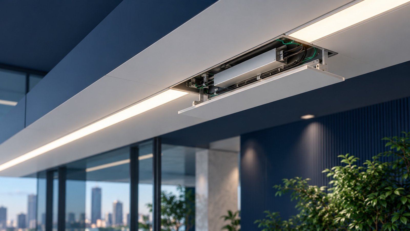
Begin with the run, not the individual fitting
Draw the complete lighting run. Mark every luminaire module, joint, feed point, end cap, support, sensor, emergency component and control zone. Note whether the line is suspended, surface-mounted or recessed. A driver placed neatly in a sample fitting may be difficult to reach when the same fitting is installed above a high counter, inside a recessed channel or beneath fixed services.
Decide which modules are replaceable and how they can be removed without disturbing neighboring sections. Some systems give access from below through a removable optical cover. Others require the whole housing to be lowered. A “linkable” product description does not by itself explain how power and control pass through the run or how a failed component is isolated.
Integral versus remote driver: the service trade-off
An integral driver is housed in or directly on the luminaire. It can reduce remote wiring and simplify a compact installation, but the available cavity may constrain heat management and service access. A remote driver can be placed in an accessible ceiling or service location, but it introduces cable routing, length and compatibility considerations. Neither arrangement is automatically superior.
Ask the supplier for the exact driver model, physical dimensions, wiring diagram and replacement procedure. Determine whether the driver can be exchanged without damaging finishes or removing several modules. Confirm the authorized cable length and conductor arrangement for the selected driver and LED load; do not extend a remote-driver lead simply because the driver fits somewhere else in the ceiling.
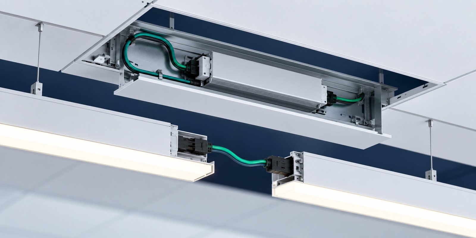
Design an accessible service zone
“Accessible” should mean a technician can reach the part safely, identify it, disconnect it and install a replacement under the building’s maintenance conditions. A driver hidden above a fixed plaster ceiling with no access hatch is not meaningfully accessible. A ceiling void that is technically open but blocked by ductwork may be equally poor.
Coordinate the service position with the architect and MEP team. Mark access hatches on reflected ceiling plans. Leave room for cable bends and connectors according to the approved instructions. Avoid locating drivers where insulation, water pipes or heat sources create unsuitable conditions. Label each driver to the run and control zone it serves so a future technician does not disconnect the wrong circuit.
Think about thermal conditions
Driver performance is influenced by the ambient conditions around it. A manufacturer may specify allowable case or ambient temperatures and mounting limitations. A driver above a hot ceiling void or enclosed tightly against insulation may operate differently from one on an open test bench. Ask for the relevant temperature ratings and a credible installation detail. For integral drivers, confirm that the luminaire housing and optical module are designed together for the proposed output setting.
Selectable-wattage products deserve extra care. A pilot at the low setting may not represent the thermal condition at the maximum approved setting. Document the final selection and test it in the installed environment where project risk warrants. Do not assume that dimming always solves a temperature or service issue.
Control wiring changes the layout
On/off, phase dimming, 0–10 V, DALI and other control approaches may need different driver models, interfaces and wiring. The control topology should be reflected in the run drawing. A long line divided into multiple zones may look continuous, yet its drivers must be assigned so each zone responds as intended. Emergency lighting or monitoring requirements can add further components and access needs.
During submittal review, ask for a schematic showing feed locations, driver count, control addresses or groups where applicable, and maximum permitted connected lengths. During commissioning, label the real installation to match the schematic. A maintenance manual that says “replace driver” without showing which driver serves which section is incomplete.
Plan for an ordinary failure, not only an ideal installation
Imagine that one module goes dark after the store opens. Can staff identify the affected run and control zone? Can a technician safely access the driver while the rest of the space operates? Is the spare part stocked and compatible with the approved module? Does replacement require repainting a ceiling or removing a neighboring sign? Walking through this scenario during design often exposes problems that are invisible in a product rendering.
Agree which parts are field-replaceable and which require factory service. Keep part numbers for LED modules, drivers, diffusers and connectors. If a new driver revision is substituted, verify electrical compatibility and dimming behavior before a site-wide purchase. Preserve the approved sample and final wiring diagram with the building record.
What to request from a supplier
- Layout drawing for the full run, including feeds, joints and end caps.
- Exact driver type and location for each configuration.
- Replacement steps and required access envelope.
- Electrical and control schematic, including any remote-driver cable limits.
- Operating-temperature and mounting instructions.
- Spare-part list and component change policy.
- One assembled sample or pilot run for installation review.
Lowcarbon’s LED linear lighting range includes continuous-run platforms with different mounting and optical options. A useful inquiry includes the total run length, ceiling type, installation height, control method and maintenance access constraints; send these through the product inquiry form. The manufacturing section explains why sample approval should lock down the critical configuration before production.
Compare service scenarios before selecting a system
Write down three realistic failures: one driver stops, one optical module is damaged and one connector at a joint becomes intermittent. For each, ask which section must be de-energized, which ceiling area must be opened and how long the repair could take. A system with a low initial price may be costly if a technician must dismantle several meters of finished ceiling to replace one part. A more modular system may have a higher component price but a simpler maintenance path.
Do not assume the answer is always to maximize field repair. In a small, accessible room, replacing a complete short luminaire may be reasonable. In a high-ceiling retail atrium with expensive access equipment, a remote service location or easily removable module can be more valuable. Match the strategy to operating hours, access cost and spare-part availability.
Document feeds and joints on the reflected ceiling plan
Long lines are often drawn as one uninterrupted stroke. Turn that stroke into real modules with real lengths. Account for expansion joints, ceiling grid changes, corners and the point where power enters the run. The driver plan should align with that module map. If two zones share a visual line, show the electrical break and control assignment so a future technician can identify it without taking down the entire run.
At each joint, verify mechanical alignment, connector engagement and diffuser continuity. A driver placed at the wrong end of a run may create extra field wiring or force an unplanned access panel. Ask the supplier to provide a project-specific run schedule with numbered modules. The installation team can then mark each module as installed and tested, making commissioning more systematic.
Ask about replacement availability
The driver is an electronic component with a lifecycle that may differ from the aluminum housing. Ask whether a service-equivalent driver will remain available and what information is needed to select a replacement. Preserve the driver label, output settings, control protocol and wiring diagram. If an original model is discontinued, do not substitute a similar-looking unit without checking electrical and control compatibility. A changed dimming curve can make one repaired section look different from the rest of the run.
Agree a sensible spare strategy. A project with many identical runs may keep a small stock of drivers, LED boards and diffusers; a one-off installation may instead rely on a documented supplier response time. Label parts by exact configuration. “Linear light spare” is too vague when the building contains several lengths, output levels and controls.
Commissioning and handover checklist
Before closing the ceiling, photograph driver locations, connector routes and labels. Verify each control zone and record any address or switch setting. Confirm that the service access shown on drawings is actually unobstructed after HVAC and other services are installed. At handover, give the owner the final module map, driver schedule, spare list, cleaning instructions and a contact for replacement parts. This small documentation package turns a beautiful line of light into a maintainable building asset.
A simple design-review exercise
Take one proposed run and trace it from power source to the final module. At every driver, joint and feed, ask three questions: can it be installed as drawn, can it be identified later, and can it be serviced without damaging adjacent work? If the answer is unknown, mark it as an open item rather than assuming the contractor will solve it on site. Repeat the exercise for the longest run and the least accessible ceiling area; these usually reveal the limiting case.
Use the exercise to compare alternative systems. One might have fewer drivers but longer secondary cables; another might put a small driver in every module. Both can work if their documented limits suit the project. The choice should balance installation labor, fault isolation, spare inventory and visual continuity, not only unit price. Ask the supplier to show a sample assembly for any unusual joint or service detail.
Frequently asked questions
Are remote drivers always easier to service?
Only if they are placed in an accessible, labelled location and installed within the approved electrical and thermal limits. Poorly located remote drivers can be harder to find than integral ones.
Can one driver power several linear modules?
Possibly, depending on the designed system. The supplier must confirm load, wiring, permitted cable length and controls for the exact combination.
Is a removable diffuser enough for maintenance?
Not necessarily. Check whether the driver, connectors and LED module can actually be reached and replaced without damage.
Should driver location appear in the submittal?
Yes. It should be shown on the coordinated drawing and reflected in the maintenance documentation.
What is the first question to ask during a mock-up?
Ask the installer to demonstrate the complete replacement path for a driver or module, not merely that the light turns on.
