 跳到内容
跳到内容 
A luminaire advertised as “UGR<19” can still feel glaring when it is aimed into a customer’s eyes, reflected by a glass shelf or installed in a different room from the conditions used to calculate the number. UGR, shielding, cut-off, luminance, beam direction and observer position describe related but different parts of visual comfort.
This guide helps retail and commercial lighting buyers use those terms correctly. We explain what to request from suppliers, what a lighting calculation must include and how to test an adjustable linear track light in the real space.
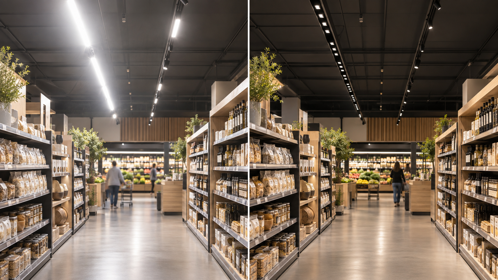
Glare is a human response, not a sticker
Glare occurs when brightness relationships in the field of view cause discomfort or reduce the ability to see. Discomfort glare can make a space tiring even when the task remains visible. Disability glare reduces visibility through light scattered in the eye. Direct glare comes from the luminaire; reflected glare can arrive from glass, polished floors, screens and packaging.
One fixture can be comfortable from one position and uncomfortable from another. Aiming and observer direction therefore matter as much as the optical component.
What UGR is designed to evaluate
Unified Glare Rating is a calculation method for discomfort glare in an interior installation. The CIE method accounts for the luminance and apparent size of luminaires, their positions relative to the observer and the background luminance. It is a room and viewing-condition result, not an intrinsic universal label belonging to a luminaire in every application.
A manufacturer can provide photometric data and tabular information under reference conditions, but the project designer should calculate the real room, luminaire layout, observer positions and directions. A website statement without room assumptions cannot guarantee the final UGR.
Why UGR<19 appears so often
UGR 19 is a familiar project criterion for certain office and work environments, so it has become a popular marketing phrase. Retail stores, galleries, circulation spaces and specialised tasks can have different requirements. The appropriate limit should come from the project standard, client brief and visual task.
Do not add UGR<19 to every RFQ by habit. First decide which observer positions and tasks need protection. A narrow-beam accent light may be outside the intended use of a simplified tabular claim yet still need careful aiming and shielding.
What cut-off angle describes
Cut-off angle generally relates to the geometry that shields a light source from direct view at certain angles. Deep-set optics, baffles, louvres and housing edges can increase shielding. However, terminology and measurement conventions can vary, so ask for a drawing showing the light-emitting surface and shielding geometry rather than relying on one number.
Greater shielding can improve comfort but may reduce optical efficiency or change the beam. The design goal is useful target light with controlled high-angle brightness, not the deepest recess regardless of performance.
Luminance is the missing clue
Illuminance in lux measures light arriving on a surface. Luminance describes brightness leaving a surface or luminaire toward the observer. Two luminaires can deliver the same shelf lux while presenting very different aperture brightness and glare.
Small intense LED points may be more visually aggressive than a larger luminous surface at the same total output. Lens images, louvre geometry and diffusion affect apparent brightness. Request luminance or high-angle intensity information when the project is sensitive.
Beam angle does not equal glare control
A narrow beam concentrates intensity, which can reduce spill if aimed correctly but can create a severe source view or bright reflection when aimed poorly. A wide beam may smooth shelf coverage but send more light into surrounding sightlines. Neither 60° nor 90° is inherently “anti-glare.”
Compare beam distribution, high-angle intensity, shielding and mounting geometry together. Use the photometric file in the real model and then test a sample.
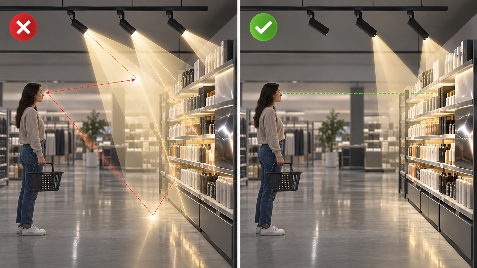
Map observer positions before aiming
Walk the customer journey and mark entrances, aisle ends, cross-aisles, queue positions, fitting-room mirrors, escalators, service counters and seated staff positions. Add lower eye heights where children or seated users are relevant. For each position, note the direction people naturally look.
Then draw the luminaire aperture and reflected surfaces in those sightlines. This exercise often finds risks that a floor-lux plan misses.
Vertical merchandise light and comfort must be balanced
Retail shelves need vertical illumination, which means luminaires are often tilted across a customer’s view. The solution is not to stop lighting shelves. It is to choose track offset, mounting height, optics and shielding that reach the merchandise without exposing the brightest angles.
Aim from the target back to the fixture. If a panel must be tilted excessively, move the track, change optic, reduce spacing or use a different luminaire rather than accepting glare.
Reflections can reverse a good design
Refrigerator doors, mirrors, polished stone, glossy packaging and screens act as secondary bright sources. Use the law of reflection as a practical check: if the fixture, reflective surface and customer eye form the right geometry, a bright image can appear even when the source is shielded directly.
Test the actual materials. Move the observer through the zone and adjust aiming while the display is complete. A calculation model with matte default surfaces may understate reflections.
How adjustable dual panels change the problem
An independently adjustable dual-panel fixture can split output between two shelf faces or a wall and central display. This may reduce the need to tilt the entire body toward one extreme direction. It also creates two apertures and two possible sightline interactions that must be checked separately.
The LL1615 linear track light for retail aisles offers 60° and 90° distributions with independent panel tilt. Select and aim each panel for a defined target. Do not treat the product’s stated UGR value as a guarantee for every room or angle.
Glare-control tools and their trade-offs
Deep optics and baffles
They shield direct views at high angles but may add size, cost and optical loss. Check cleaning access and finish reflectance.
Diffusers
They enlarge the luminous area and soften LED images, but can widen distribution or reduce intensity. Evaluate shelf reach and efficiency.
Louvers
They control specific angles and can improve visual comfort. Poorly designed louvres may create striations or reduce uniformity.
Track position
Moving the rail changes every aiming relationship. It can be more effective than adding an accessory after installation.
Lower output and closer spacing
More moderate-intensity sources can reduce harshness, but extra fixtures add cost and ceiling density. Compare complete layouts.
Controls
Dimming can balance brightness after commissioning, but it cannot correct a directly visible aperture or bad reflection geometry by itself.
What to request from the supplier
- Photometric file for the exact wattage and optic
- Complete-luminaire dimensions and luminous-opening geometry
- High-angle intensity or luminance information where available
- UGR tables with stated room and reflectance assumptions
- Drawings of baffles, louvres and cut-off geometry
- Accessory impact on lumens and beam distribution
- Fixture rotation and tilt limits
- Glare-related test conditions and report source
- Representative sample for site evaluation
Do not compare one supplier’s UGR table with another supplier’s marketing headline. Align the conditions first.
Mock-up procedure
- Install the exact production-intent luminaire at real height and offset.
- Add actual shelves, signs, glass and glossy products.
- Aim to target planes using a documented sequence.
- Measure vertical shelf light and relevant horizontal tasks.
- Stand at every mapped observer position.
- Check direct source views and reflected images.
- Compare optics or shielding under equal target illumination.
- Photograph final settings and record body and panel angles.
- Repeat after nearby luminaires are operating.
- Obtain design and end-user approval before full installation.
Common mistakes
Using a product UGR as a universal promise
UGR depends on the installation. Request assumptions and calculate the project.
Judging glare from directly below
Customers usually see track lights from oblique positions. Walk entrances and aisle ends.
Reducing glare by reducing all light
Lower output may make shelves dull without removing the visible bright source. Fix geometry first.
Ignoring reflected glare
Glass and glossy surfaces can create the dominant source image. Include real materials.
Aiming before merchandising
An empty room is not the final visual condition. Commission after displays are installed.
Commissioning record
Record luminaire model, optic, power setting, track position, rotation, panel tilt, dimming level, target measurements, observer checks and approved photographs. Mark a reference bay and train authorised staff how to return moved fixtures to an approved range.
Our sample-approval guide provides a structure for these records, while our retail lighting guides explain vertical target selection.
Final recommendation
Use UGR as an installation calculation, cut-off as optical geometry and the site mock-up as the final reality check. A comfortable design keeps the brightest apertures and reflections away from common sightlines while still delivering sufficient light to merchandise.
If you send us your section drawing, track position, shelves, observer views and target illumination, we can help select an optic and prepare a sample. We prefer to test useful shelf light and comfort together rather than promise “anti-glare” from one isolated number.

