 跳到内容
跳到内容 
“Flicker-free” is one of the most common claims on LED driver and luminaire quotations, yet it is often supported only by a slow-motion phone video or one percentage measured under unknown conditions. That is not enough for a commercial project. Temporal light modulation changes with the driver, LED load, mains supply, dimming method and output level, so the exact configuration and test method matter.
This guide helps lighting buyers, designers and importers understand flicker percentage, PstLM and SVM without turning the RFQ into a research paper. We explain what each metric is trying to show, what it does not show, and how to approve an LED track or linear light across the operating range.
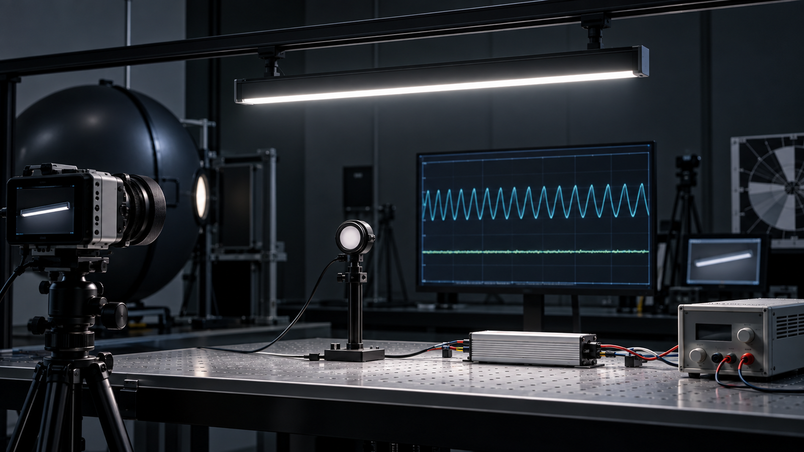
Why LEDs can produce temporal light modulation
LEDs respond quickly to changes in current. The driver converts the incoming supply into controlled output for the LED module, and imperfections or deliberate control in that current can appear as light modulation. Sources include rectified mains ripple, inadequate smoothing, pulse-width modulation, low-frequency control, unstable compatibility between dimmer and driver, and operation below the driver’s stable load.
Not all modulation is equally visible or harmful to the task. Frequency, depth, waveform shape, duty cycle, movement and observer sensitivity all matter. A single “flicker percentage” cannot describe every effect.
Visible flicker and stroboscopic effect are different
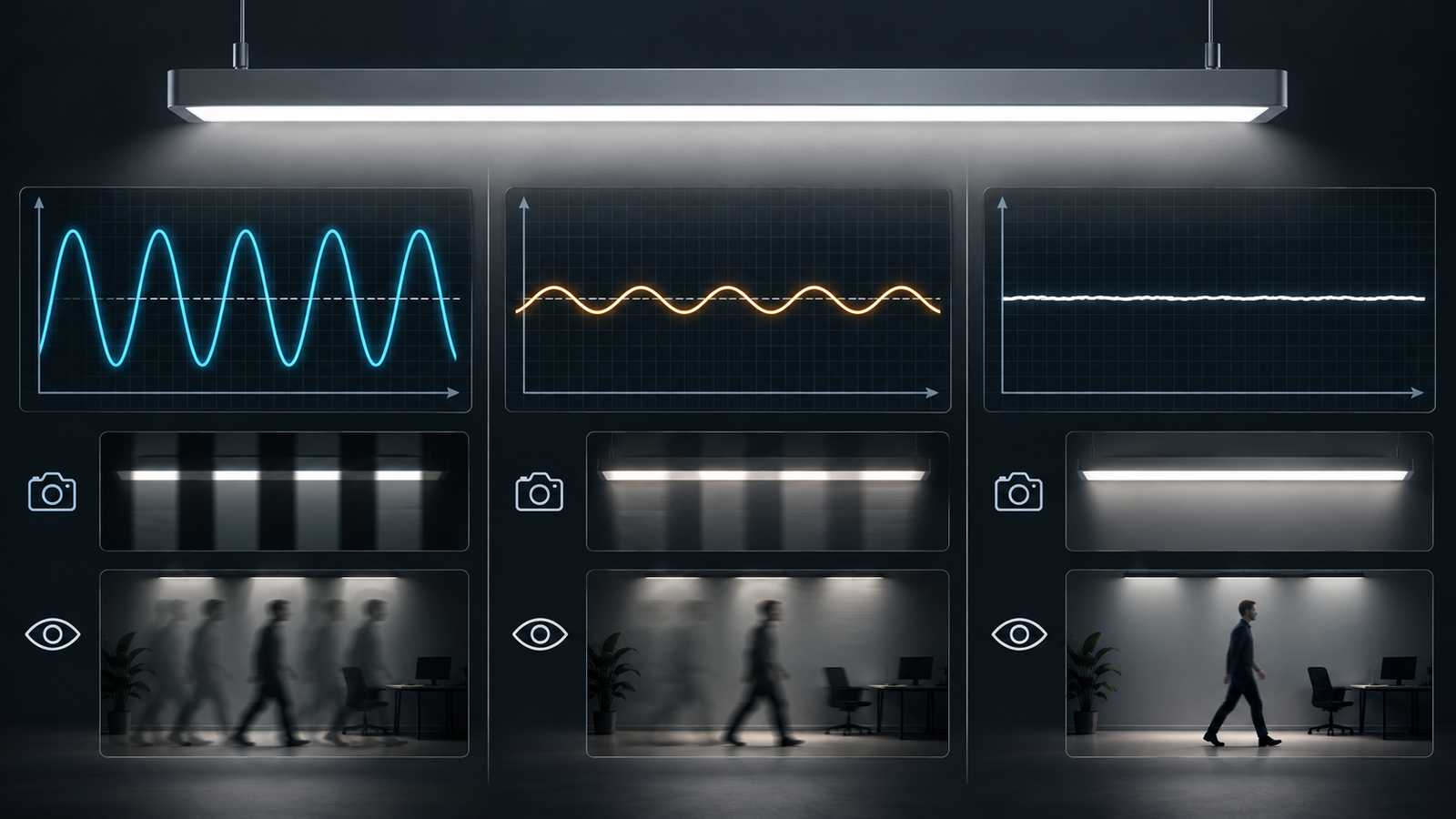
Visible flicker is the perception of unsteadiness when both the observer and environment are relatively static. Stroboscopic effect is a change in how movement is perceived under modulated light. A rotating object, moving hand, scanning process or person walking can reveal effects that are not obvious while staring at a stationary shelf.
This distinction matters in retail and commercial spaces. A luminaire may look stable on a wall but produce banding in video or altered motion perception at a checkout, escalator or moving display. Testing should reflect the real application.
What flicker percentage tells you
Percent flicker, sometimes called modulation depth, compares the maximum and minimum light level in a cycle. A waveform that falls close to zero can have a high percentage, while a shallow waveform has a lower percentage. The calculation is easy to understand, which is why it appears frequently on quotations.
Its weakness is that it does not properly account for frequency or complex waveform shape. Two products can have the same percentage but create different visual effects because one modulates slowly and the other quickly. Use it as one descriptive value, not a universal pass/fail metric.
What flicker index tells you
Flicker index considers the area of the waveform above and below the average during a cycle. It provides more information about waveform shape than percent flicker, but it still does not fully predict perception across all frequencies and conditions. Some suppliers report it without stating the sampling method, measurement duration or light level.
If flicker index is specified, ask for the waveform and test setup so the number can be interpreted. Do not compare values taken by different instruments under undisclosed settings as if they were identical.
What PstLM means
PstLM is a short-term light-flicker metric based on a light flickermeter method and intended to relate to human perception of visible flicker. EU ecodesign rules define PstLM = 1 as a point where the average observer has a 50% probability of detecting flicker. For covered LED and OLED mains light sources at full load, the regulation states a PstLM limit of 1.0.
Scope and test conditions matter. Do not copy that limit onto every luminaire and dimming level without checking whether the product is a light source, containing product or other configuration under the current rules. Use the official EU regulation and competent compliance advice for legal decisions.
What SVM means
SVM is the stroboscopic visibility measure. It addresses perception of stroboscopic effects when objects or observers move. In the same EU framework, SVM = 1 represents the visibility threshold for an average observer, and a limit of 0.4 at full load is stated for covered LED and OLED mains light sources, with specified exceptions.
A low PstLM result does not automatically guarantee a low SVM result because the metrics address different perceptual effects. Ask for both where the application and regulatory scope make them relevant.
Why a phone camera is not a measurement instrument
Slow-motion video can reveal banding and is useful as a quick warning, but the result depends on frame rate, shutter, rolling shutter, exposure, camera processing and the relationship between sampling and modulation frequency. A clean video does not prove good performance, and visible bands do not quantify PstLM or SVM.
Use a suitable light sensor and instrument with documented bandwidth, sampling and calculation method. Keep the phone test as an application check for video-sensitive locations, not as the compliance report.
Full output is only one operating point
Drivers often behave differently when dimmed. A product with excellent full-load data may show deeper modulation, dropout or irregular pulses near minimum output. If the store normally runs at 60%, a full-output report does not validate the real condition.
Define test points such as 100%, 75%, 50%, 25%, the specified minimum and just above switch-off. For tunable-white or multi-channel products, test representative and worst-case channel combinations. State whether measurements are taken after thermal stabilisation.
The dimming method changes the result
Phase-cut dimming
The dimmer and driver interact through the mains waveform. Leading-edge or trailing-edge method, connected load, number of drivers and dimmer model can affect stability. Test the complete intended combination and circuit quantity.
0–10V dimming
The driver receives an analogue control signal, but its internal output method determines temporal modulation. Confirm behaviour across the voltage range and at the cable conditions expected in the project.
DALI dimming
DALI sends digital commands; the driver still decides how LED current is controlled. DALI compatibility does not itself guarantee low temporal modulation. Request performance data for the exact certified driver and dimming levels.
Pulse-width modulation
PWM rapidly switches current on and off to control average output. Frequency and duty cycle strongly affect temporal behaviour. High frequency can reduce some visible effects, but the application, camera use and measurement method still matter.
Mains voltage and frequency must be stated
Test results at one supply condition may not represent another. Ask for nominal voltage and frequency, tolerances and any conditions under which the driver changes operating mode. European and Australian projects commonly use 50 Hz supplies, while products may also be marketed for 60 Hz systems. The driver design should be evaluated for the intended market.
Power quality, shared loads and controls can introduce site interactions. A laboratory pass is necessary evidence, but a representative circuit pilot can reveal system problems.
Driver and LED load must remain a controlled pair
The same driver model can operate different LED voltages or currents, and the same luminaire housing can contain different drivers. Temporal performance belongs to the combination. Record driver model, firmware where relevant, output current, LED board, series or parallel arrangement and thermal condition.
If the factory substitutes a driver, repeat the impact assessment. Similar wattage and physical size do not make drivers interchangeable for flicker, safety, EMC, dimming or lifetime.
What buyers should request in a test report
- Complete product and model identification
- Driver make, model and output setting
- LED module and electrical load
- Input voltage and frequency
- Dimming method, controller and command level
- Ambient and stabilisation condition
- Instrument, sensor and measurement method
- Waveform image and modulation frequency information
- PstLM and SVM where applicable
- Percent flicker or modulation depth if used
- Results at full output and specified dimmed levels
- Test date, laboratory and report revision
The report should let another competent person understand what was measured. A spreadsheet containing numbers without setup or waveform is difficult to audit.
Application risks to consider
Retail stores contain movement, glossy packaging, rotating displays, escalators, barcode scanning and customers recording video. Offices and education spaces involve long exposure and screen use. Warehouses and production areas can contain moving machinery. Photography studios, broadcast spaces and showrooms may be especially sensitive to camera banding.
Do not claim one universal “human-safe flicker” result from a marketing label. Define the task, applicable requirements and project acceptance values with the designer or specialist.
How to run a sample approval
- Freeze the driver, LED load, control method and market configuration.
- Measure at intended voltage and frequency.
- Test full output, common scenes and minimum level.
- Record PstLM, SVM and waveform where relevant.
- Connect the expected number of drivers or a representative circuit.
- Check the actual dimmer or control system.
- Observe the sample in a real mock-up with movement and cameras.
- Save the approved results with the golden sample.
When several wattages share one driver family, decide whether each output setting needs verification. A DIP or selectable-current position can change both load and modulation behaviour.
Common quotation traps
“Flicker-free driver” without a model number
Require the exact driver and lock it in the bill of materials. Otherwise the claim cannot be traced to production.
One value with no operating condition
Ask for input, output, dimming level, frequency and method. A number without conditions is not comparable.
Testing only the driver
The LED load and complete luminaire configuration affect operation. Prefer production-intent assembly data.
Testing only at 100%
Low-end dimming often presents the greatest risk. Approve the range that occupants will use.
Using a camera video as a certificate
Video is a useful demonstration, not a standardised metric. Request instrument data and laboratory records.
How flicker belongs in the purchase order
State the exact metric, limit, operating points, supply condition, test method, sample quantity and report required. Link it to the approved driver and LED configuration. Define whether production changes require retesting. If camera performance matters, add a project-specific video test using stated camera settings.
Our RFQ and sample-approval guide helps lock the configuration before production. For controls, see our comparison of DALI, 0–10V and phase-cut dimming.
Final recommendation
Replace the vague question “Is it flicker-free?” with “What temporal-light metrics does the exact luminaire achieve at our supply and dimming levels, and how were they measured?” That question produces evidence a designer and buyer can use.
If you send us your voltage, control method, minimum output, driver requirement and application, we can prepare a production-intent sample and organise the relevant measurements. We will not treat a slow-motion phone video as the whole answer.

