 跳到内容

Curved LED linear lighting can make a ceiling layout follow architecture rather than forcing every luminous line to be straight. A rounded reception zone, loop, wave or sweeping corridor can look compelling in a drawing. Turning that drawing into a reliable luminaire, however, requires more than specifying “bendable linear light.” The project team must agree the curve geometry, support points, electrical feeds, diffuser continuity, finish and service access before manufacture.
This guide is for architects, contractors and importers commissioning a custom curved or bendable LED linear system. “Curved” may describe pre-formed rigid modules, a flexible profile or a joined arrangement, depending on the product. Do not assume a particular construction or minimum radius from a marketing image. Use the exact supplier drawing and a physical sample to establish what can actually be built. The images here include a production-bench photograph and a conceptual product montage; neither is a substitute for an approved engineering drawing.
Turn the sketch into coordinates
A freehand curve communicates design intent but not enough information to fabricate a repeatable system. Provide a scaled plan with centerline, start and end points, radius or control points, ceiling height and the direction of light emission. If the line changes plane or turns a corner, show that in an elevation or 3D view. Label where segments join and where the electrical feed enters. Small ambiguities at this stage become visible misalignments when the fixture is suspended in a large open space.
Confirm whether the architect is measuring the inside edge, outside edge or luminous centerline of the curve. A profile has width, so those paths differ. For a closed loop, show the required overall dimensions and how the last joint closes. For an open wave, provide the endpoints and tangent direction at each end. If ceiling services or sprinklers cross the route, coordinate them before the fixture shape is frozen. A beautiful rendering can hide a structural or electrical conflict.
Ask the manufacturer to return a dimensioned shop drawing rather than only a price. Review the tolerances that matter for the visible result: joint gap, alignment, surface finish and suspension positions. Approve the drawing with the architect and installer before production. If the site changes, do not quietly stretch or compress a curved layout; revise the drawing and assess support and electrical consequences.
Understand the proposed construction
The phrase “bendable LED linear light” can refer to different systems. Some profiles are formed to a specified radius in the factory and arrive as rigid curved pieces. Others can be shaped within a limited range on site. A third approach uses short straight sections to approximate a curve. Each has different joint appearance, shipping size and service behavior. Ask the supplier which construction applies to the quoted product and what evidence supports the minimum radius and repeatability.
Review the cross-section and diffuser. A continuous luminous appearance may be interrupted by joins, end caps, suspension clips or a change in curvature. A shallow curve can conceal short segments; a tight curve can make faceting obvious. The project team should view a real sample at the likely viewing distance, switched on and off. If the design relies on a seamless line, define what “seamless” means in an acceptance note rather than assuming everyone imagines the same result.
The profile finish is also part of the architecture. Check whether the curve process affects coating consistency or introduces surface marks. If the system is supplied in custom color, approve a physical sample. A black profile may visually recede against an exposed ceiling; a white or metallic finish may become a graphic line. Lighting and finish should be reviewed together, especially where the unlit fixture is visible in daylight.
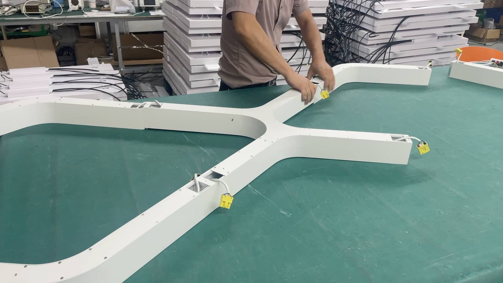
The workshop image shows why connections and geometry deserve explicit review. It is not a scale drawing; the exact supplied product still needs approved dimensions and wiring details.
Coordinate suspension and ceiling structure
A curved suspended luminaire needs support points that follow the geometry and carry the load safely. Ask for the proposed suspension schedule, point loads and adjustment method for the exact system. The structural designer and installer must confirm the building fixing. A rail of lights hanging from a decorative ceiling panel without a verified load path is not an acceptable assumption. Coordinate sprinkler, HVAC, acoustic and maintenance access at the same time.
Suspension height affects both visual appearance and useful light. A low curve can be dramatic but may obstruct views or make glare more noticeable. A high curve may look elegant yet provide little targeted light on work surfaces. Establish the intended height on a section drawing and mock up a representative area. Check how the curve reads from entrances and upper levels, not only from directly beneath it. In an office or hospitality setting, different vantage points can reveal joints and support wires that a plan hides.
For a recessed curved system, the coordination is different but equally important. The ceiling aperture must follow the approved centerline and accommodate the profile and driver access. The trade sequence should be agreed so the ceiling contractor does not cut an opening from an early concept sketch. A pilot segment should be fitted before the full opening is made. If the system crosses a ceiling expansion joint or changing substrate, seek a project-specific detail.
Plan electrical feeds and controls as sections
A long curved line may contain several electrical sections even when it looks continuous. Ask where the feeds enter, where drivers sit and how each section is connected and protected. The electrical designer should review voltage, circuiting, cable route and any local code requirements. Do not assume that every curved segment can be powered from a single end or that all joints carry power. The supplier should provide a wiring diagram tied to the approved drawing.
Decide whether the whole shape dims as one scene or whether zones require independent control. A loop around a reception desk may be one visual object; a wave crossing different work areas may need multiple control groups. Test the proposed driver and controller on a production-intent segment, including the intended low-end setting. If several sections are joined, look for visible brightness or color changes at boundaries. Document the approved CCT and control state.
Service access must be designed in, not discovered after installation. Where can a failed driver be reached? Can an individual curved module or diffuser be replaced without taking down the entire system? Are spare curved sections practical to store and transport? Ask these questions before accepting a custom quotation. Replacement availability can be especially challenging for a unique radius or finish, so keep the approved drawings and supplier revisions.
Review the lit line, not just the profile
A curved luminaire can serve different purposes: a visual feature, ambient layer, wayfinding element or task-related light. Define the primary purpose. If the curve is mostly decorative, another layer may still be required to illuminate desks or merchandise. If it is expected to provide useful light, request photometric data for the proposed emission direction and calculate the actual room conditions. A smooth visual line does not automatically mean adequate illumination below.
Inspect diffuser uniformity and the appearance of corners or joints. LEDs that are hidden on a straight segment may become visible at a tight bend if the optical geometry changes. A joint can appear dark or bright. Check from the main room viewpoints under the intended dimming scene. If the project uses a textured ceiling or glossy floor, review reflections and surrounding contrast as well. The curve can draw attention to any visible irregularity.
A conceptual montage can help the team agree on design intent, but it must be labeled as such. It should not be presented as a photograph of an installed customer project or evidence of measured performance. The actual workshop sample and site mock-up should control the final appearance. Keep rendered imagery separate from technical approval records.
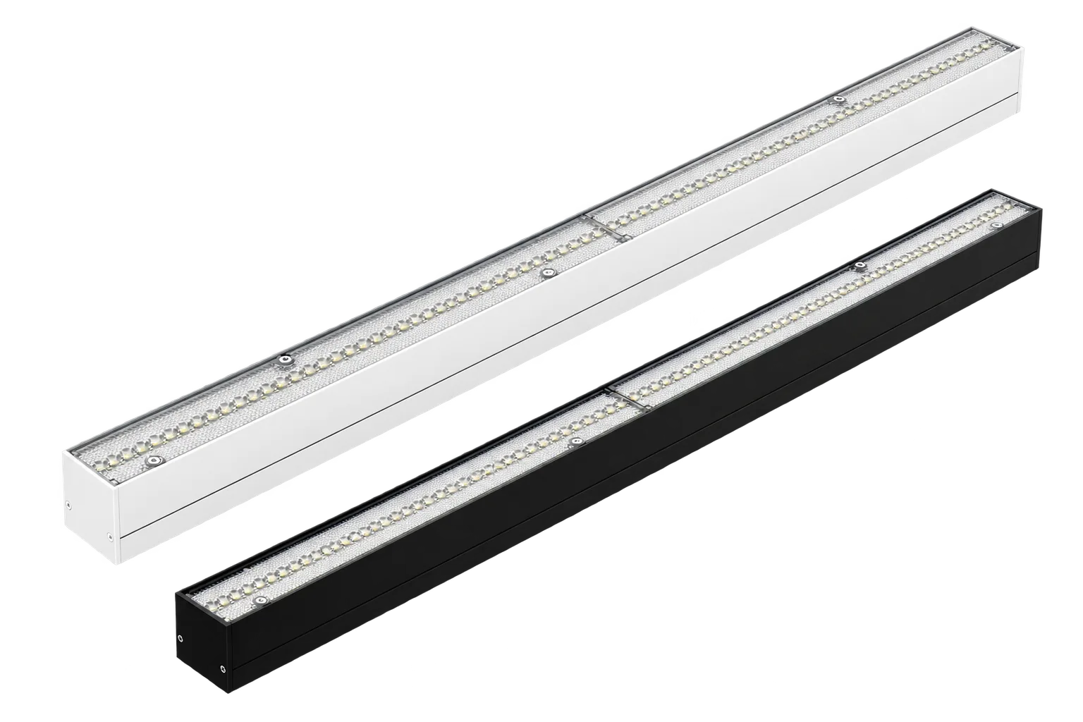
A straight linkable system is a useful comparison: it usually has different joint and transport logic from a custom curve. Choose based on the architectural path and maintenance plan, not visual novelty alone.
Package and install in the right sequence
Curved pieces can be more vulnerable to transit damage or confusion than standard straight lengths. Ask how segments will be labeled, protected and packed. A unique module should carry a drawing reference and orientation mark. For a loop, the order of assembly matters; numbered pieces and a clear plan can save site time. Confirm the maximum package size against freight and building access, especially where lifts or narrow corridors are involved.
Before full production, request a sample of the most difficult portion: the tightest radius, a representative joint and the proposed diffuser. Review its dimensions and finish unlit, then energize it to check continuity. If the order is large, a factory pre-assembly or fit check can expose mistakes before shipment. Document what was accepted and what changed. The supplier and installer should use the same revision of the drawing.
On site, survey the suspension points and power feeds before the fixture arrives. Stage pieces in labeled order, protect visible surfaces and follow the supplier’s installation instructions. Commission the electrical sections and controls after mechanical alignment. Photograph the completed system from the approved viewpoints and compare it with the sample criteria. A small deviation in suspension height across a curve can be visually obvious.
Compare custom curve with simpler alternatives
Custom geometry is worthwhile when it supports the architecture or brand experience. It also adds design, fabrication, packaging and maintenance work. Compare the proposal with straight linkable runs, segmented polygonal layouts or a smaller feature curve combined with standard general lighting. A simpler system may better suit a tight programme or a building expected to change frequently. Do not default to a curve just because the concept render looks attractive.
Prepare a total-cost review: design and shop drawings, prototype, custom tooling or forming, drivers, controls, supports, shipping, installation, commissioning and spare parts. Confirm what is included in the quotation. A low unit price can hide engineering and site coordination costs. Lowcarbon’s product center shows the wider linear lighting range, and the suspended LED linear lighting checklist covers related suspension questions for conventional runs.
Common mistakes to avoid
- Supplying a freehand curve without a dimensioned centerline.
- Confusing factory-formed curved modules with products that can bend freely on site.
- Ignoring visible joint and diffuser continuity at the tightest radius.
- Approving suspension locations before checking the real structure.
- Treating a decorative luminous line as sufficient task lighting without analysis.
- Omitting driver access and spare-section planning.
- Shipping unlabeled unique segments to a complex site.
- Presenting a concept montage as a verified installed project.
Frequently asked questions
Can every bendable linear light form any radius?
No. The minimum radius and bending method depend on the exact profile and construction. Obtain the supplier’s current limits and approve a sample of the tightest proposed curve.
Is a curved system always seamless?
No. Segment joints, diffusers, support points and electrical sections can remain visible. Define an acceptance standard and inspect a lit sample from the intended viewing distance.
Should a curved light provide the room’s general illumination?
Only if the design and photometric analysis show it meets the real task. A curve may be primarily an architectural feature and need a separate lighting layer.
What should be on the shop drawing?
Include centerline geometry, dimensions, segment and joint locations, suspension points, feed positions, driver sections, profile cross-section, emission direction, finish and revision.
What must the buyer keep for later repairs?
Retain the approved drawings, sample reference, component codes, driver and control information, installation sequence and spare-section plan. A unique shape is difficult to reproduce from a photograph alone.
Final recommendation
Commission curved LED linear lighting as a small architectural system, not a standard length with a decorative bend. Freeze the geometry, test the difficult joint and radius, verify support and electrical sections, then approve a lit sample. Clear drawings and records make the custom visual idea buildable and maintainable.
