 跳到内容
跳到内容 
An LED linear light failure is not always an LED-board failure. A dark section, reduced output, color shift, intermittent restart or failed control response can originate in the driver, connector, wiring, thermal path, control system, emergency circuit or incoming supply. At LCB Light, we begin by defining the failure pattern and preserving evidence before parts are changed.
This article provides a practical triage method for project owners, distributors and contractors. Electrical investigation must be completed by qualified personnel using safe isolation procedures and the manufacturer’s instructions. The goal is to narrow the cause, not to encourage unsafe live testing.
Describe the symptom before diagnosing it
Record whether the luminaire is completely dark, dim, pulsing, discolored, partly illuminated or unable to dim. Note when the failure began, whether it changes after warm-up and whether nearby fittings are affected. Photograph labels, connections and any visible damage before disassembly.
One failed module in a long run suggests a local component or connection. An entire zone failing together points toward supply, control, protection or a shared feed. A repeated pattern across one production batch may indicate a component or assembly issue that deserves broader containment.
Rule out supply and control causes
Confirm that the correct circuit is energized, protective devices are set correctly and the supply voltage matches the product. Check switches, sensors, contactors, central controls and emergency interfaces. For dimming systems, verify addressing, control voltage or phase compatibility. A control command at zero can look identical to a failed driver.
Do not bypass safety devices or connect incompatible test supplies. Use the wiring diagram and compare the affected fitting with a known working unit under controlled conditions.
Driver failure patterns
Drivers may fail open, operate intermittently, reduce output, enter protection or lose control communication. Heat, surge events, incorrect input, output mismatch, moisture and component aging can contribute. A visibly damaged driver is useful evidence, but many electrical faults leave no obvious external mark.
Record the exact brand, model, input/output rating, dimming protocol and production code. If a replacement driver restores operation, keep the original for analysis. Confirm that the replacement current, voltage range, power, isolation, control method and enclosure conditions match the approved design.
LED board and optical symptoms
A single dark segment can result from an open LED, board connector or solder joint, depending on circuit design. Progressive color shift, localized browning or reduced output can point toward excessive junction temperature, contamination or optical-material degradation. Examine the diffuser, board and reflector without destroying evidence.
Do not judge LED lifetime from the package claim alone. The complete luminaire’s temperature and drive current determine operating stress. Compare the failure with a retained sample and with other fixtures from the same batch.
Thermal causes and cycling
If a luminaire works when cold and later dims, cycles or shuts down, investigate thermal protection and installation conditions. Blocked airflow, insulation contact, excessive ambient temperature, wrong driver location, high drive current or poor contact between the board and heat sink can raise temperature.
Measure at manufacturer-defined points after thermal stabilization and compare with the approved test condition. Surface temperature alone is not the LED junction temperature, but consistent measurements can reveal abnormal sections. Check mounting orientation because a product suitable for suspended use may behave differently in a confined recess.
Wiring, connectors and continuous runs
Continuous systems add joints, through-wiring, plug connectors and multiple feeds. A partially seated connector, reversed polarity on a low-voltage section, damaged conductor or loose neutral can isolate one module or cause intermittent operation. Inspect strain relief, pin condition and wire routing at joints.
Long runs must respect circuit current and the manufacturer’s maximum run. If failures cluster near a feed or at the end of a run, review voltage drop, connector loading and driver arrangement. Our continuous light-line guide covers the mechanical and electrical coordination needed before installation.
Build a useful failure report
- Project, location and installation date
- Luminaire, driver, LED board and control identifiers
- Batch/date codes and failed quantity
- Failure symptom, timing and environmental condition
- Photos before and after safe removal
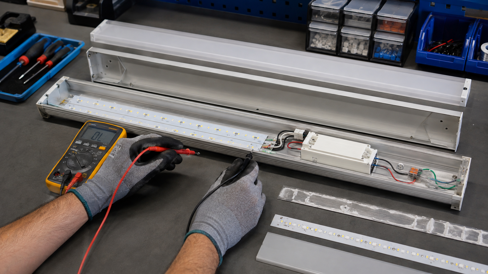
- Supply and control measurements by qualified personnel
- Parts swapped and the result of each controlled test
- Returned samples and requested corrective action
For multiple failures, calculate the affected quantity by batch and operating zone. This helps distinguish isolated damage from a repeatable production or application problem.
Illustrative fault-pattern comparison
Suppose three fittings fail in one week. Unit A is completely dark and follows its driver when the component is tested safely in a controlled setup. Unit B flickers only after 40 minutes in a confined recess. Unit C loses one module after a connector is moved. Treating all three as “LED failure” would hide different mechanisms: likely driver, thermal and connection paths.
The site should contain the risk, preserve parts and record each case separately. If all three share a batch or installation detail, the manufacturer can then decide whether wider inspection is needed. Failure quantity without denominator is also misleading: three failures among 30 units and three among 3,000 require different commercial responses.
Use a simple cause-and-evidence matrix
| Possible cause | Evidence to collect | Controlled comparison |
|---|---|---|
| Supply/control | Voltage, commands, affected zone | Known working circuit or controller condition |
| Driver | Model, output, temperature, returned unit | Compatible known-good driver |
| LED/board | Dark segments, discoloration, board code | Approved sample and electrical test |
| Thermal | Warm-up timing, ambient, installation | Approved mounting condition |
| Connector/wiring | Pin, strain, continuity, location | System drawing and adjacent module |
Qualified personnel should determine the safe test method.
Corrective action should address recurrence
A proper corrective-action report describes the confirmed cause, immediate containment, affected scope, permanent change and verification. If the cause is not confirmed, state the remaining hypothesis and planned test. Avoid claiming that replacing a part proves why it failed; replacement may restore function without establishing root cause.
Feed lessons back into the next order
Update drawings, installation instructions, inspection points, component specifications or thermal limits as appropriate. At LCB Light, we want warranty findings to improve repeat production. The buyer should also update site practices if insulation, wiring, surge conditions or cleaning contributed. A shared evidence trail makes that discussion factual and reduces repeated field labor.
When to expand the investigation
One isolated failure may need a unit-level report. Repeated failures across a batch, safety-related damage, abnormal heat or a rapidly increasing rate should trigger broader containment and expert review. Identify potentially affected serial or date codes, pause installation if appropriate and agree on sampling before parts are discarded. The project owner and qualified technical parties should decide the response based on risk.
Do not extrapolate a root cause from social-media photos or one dismantled sample. Keep chain of custody for returned units and compare failed and working products from the same batch. A measured, proportionate escalation protects occupants and avoids both underreacting to a systemic fault and overreacting to unrelated site damage.
Practical note: keep packaging and shipping evidence when damage is discovered on arrival. Bent profiles, cracked boards or displaced connectors can result from transport rather than electrical operation. Photograph cartons, pallet condition and impact marks before unpacking the full batch, and separate logistics claims from in-service reliability analysis.
Turn the technical finding into a purchasing decision
A useful specification states the application, exact luminaire configuration, operating conditions, required evidence and acceptance method. At LCB Light, we encourage buyers to separate mandatory performance from preferences and to approve one production-intent sample. That makes quotations comparable and gives production inspectors a clear reference.
Keep the approved product code, drawing, driver, optic, test file and finish in one project package. If any of those items changes, review the effect before shipment. This simple change-control step protects the result more effectively than adding more marketing adjectives to the purchase order.
Our after-sales approach
At LCB Light, a useful warranty conversation starts with traceable evidence. We compare the failed configuration with the approved sample and production record, then agree on containment, analysis and corrective action. For an urgent site, replacement parts may restore service while returned samples continue through root-cause analysis.
For future orders, the lesson should become a controlled improvement: revised component, wiring instruction, thermal limit, inspection point or site requirement. Closing the loop is more valuable than replacing one unit without learning why it failed.
Frequently asked questions
Should I replace the driver first?
Not automatically. First verify supply, controls, connections and the symptom pattern. A controlled driver substitution can be diagnostic when the replacement is electrically compatible.
Why does only part of a continuous line fail?
That section may have its own driver, LED circuit or connector. Use the system drawing to identify where power and control are divided.
Can overheating damage the diffuser as well as electronics?
Yes. Excess heat can affect optical materials, wiring and drivers. Investigate the complete thermal condition rather than replacing only the visibly damaged part.
Discuss Your LED Linear Lighting Project
Share your layout, mounting height, target light level, optic, control and destination-market requirements. The LCB Light team can help you prepare a project-specific configuration and sample plan.

